Search This Blog

Wednesday, November 25, 2015

Cisco ASA syslog through IPsec tunnel

In this scenario we have a Cisco ASA which connected to remote branch using IPsec tunnel and we want to send all syslog messages to a remote syslog server through the IPsec tunnel.
Network diagram:


For this we will have to use the management interface (and no I don’t mean the dedicated management interface) which can be found under Device Management -> Management Access -> Management Interface:


This feature instructs the ASA which interface to use for management purposes such SNMP, Syslog, icmp replay and more.

When you try to ping the ASA interface you will get an answer only if you reside on the same interface which you tried to ping (and of course allow icmp under Device Management -> Management Access -> icmp).

So back to remote syslog configuration, first configure the interface which you want the ASA will use to send syslog messages, here I select the INTERNAL interface (as in the image above).

Then configure the syslog server as follow:


Note that I choose interface INTERNAL rather than EXTERNAL.

In CLI you may see the following message:

ASA-1(config)# logging host INTERNAL 10.2.0.100
WARNING:  configured logging host interface conflicts with route table entry

Just ignore it, this is a cosmetic issue following bug CSCur60060.

Using Management interface will allow also remote access client to connect to the ASA using ASDM or SSH.

Friday, November 20, 2015

Cisco ASA L2L with all traffic default route

Cisco Adaptive Security Appliance Software Version 9.5(1)
Device Manager Version 7.5(1)

This is the network topology:
All traffic originated from office 2 network (192.168.20.0/24) should be route through ASA1, and going to internet will be NAT using office 1 external IP (10.1.0.1).

ASA1 Configuration
access-list ACL_IPSEC_ASA2 extended permit ip any4 192.168.20.0 255.255.255.0
!
#Note that tunnel group must be the peer IP address
tunnel-group 10.2.0.1 type ipsec-l2l
tunnel-group 10.2.0.1 ipsec-attributes
 ikev1 pre-shared-key <PRE-SHARED_KEY>
!
crypto map VPN_MAP 10 match address ACL_IPSEC_ASA2
crypto map VPN_MAP 10 set pfs
crypto map VPN_MAP set reverse-route
crypto map VPN_MAP 10 set peer 10.2.0.1
crypto map VPN_MAP 10 set ikev1 transform-set ESP-AES-256-SHA ESP-AES-128-SHA ESP-AES-128-MD5 ESP-AES-192-SHA ESP-AES-192-MD5 ESP-AES-256-MD5 ESP-3DES-SHA ESP-3DES-MD5 ESP-DES-SHA ESP-DES-MD5
crypto map VPN_MAP interface EXTERNAL
!
same-security-traffic permit inter-interface
same-security-traffic permit intra-interface
!
object network OG_ASA1_NETWORK
 subnet 192.168.10.0 255.255.255.0
!
object network OG_ASA2_NETWORK
 subnet 192.168.20.0 255.255.255.0
!
nat (any,any) source static OG_ASA1_NETWORK OG_ASA2_NETWORK destination static OG_ASA1_NETWORK OG_ASA2_NETWORK unidirectional
nat (any,EXTERNAL) source dynamic OG_ASA2_NETWORK interface
!
route EXTERNAL 0.0.0.0 0.0.0.0 1

ASA2 Configuration
access-list ACL_IPSEC_ASA1 extended permit ip 192.168.20.0 255.255.255.0 any4
!
#Note that tunnel group must be the peer IP address
tunnel-group 10.1.0.1 type ipsec-l2l
tunnel-group 10.1.0.1 ipsec-attributes
 ikev1 pre-shared-key <PRE-SHARED_KEY>
!
crypto map VPN_MAP 10 match address ACL_IPSEC_ASA2
crypto map VPN_MAP 10 set pfs
crypto map VPN_MAP set reverse-route
crypto map VPN_MAP 10 set peer 10.1.0.1
crypto map VPN_MAP 10 set ikev1 transform-set ESP-AES-256-SHA ESP-AES-128-SHA ESP-AES-128-MD5 ESP-AES-192-SHA ESP-AES-192-MD5 ESP-AES-256-MD5 ESP-3DES-SHA ESP-3DES-MD5 ESP-DES-SHA ESP-DES-MD5
crypto map VPN_MAP interface EXTERNAL
!
same-security-traffic permit inter-interface
same-security-traffic permit intra-interface
!
route EXTERNAL 10.1.0.1 255.255.255.255 10.2.0.2 1 

Thursday, November 19, 2015

VPN site-to-site between Cisco ASA to Fortigate - Part 1

In the following post I will demonstrate a VPN site-to-site (L2L) configuration between Cisco ASA and Fortigate appliances.

These are the customer demands for the following setup:
- VPN site-to-site between Office 1 and Office 2
- All traffic from Office 2 should pass-through office 1
- When Office 2 goes to the internet they will using Office 1 external IP

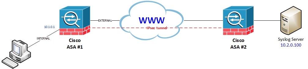
This is my lab setup:


Let’s start with the Fortigate configuration,
VPN -> IPsec ->Tunnels
Type in a name for this tunnel and select Custom VPN Tunnel (No Template)


Fill in the required information, type in the remote IP address (10.1.0.1), fill in the pre-shared key and select phase 1 proposal, here I choose IKEv1 with AES192 and SHA1 using DH group 2 (1024bit) and key lifetime of 86400 seconds (24 hours).


Continue filling phase 2 selectors, type in the local networks, in this case I summarize Office 2 networks to 192.168.48.0/21, and remote networks which in my case should be 0.0.0.0/0.0.0.0 in order to route all traffic through the VPN tunnel, and phase 2 proposal - here I choose again AES192 with SHA1 and DH group 2, also check PFS and type in the key lifetime to 86400 seconds.


Note that I removed all other options in phase 1 and 2 proposals and leave only AES192 with SHA1.

Now go to Policy & Objects -> Objects -> Addresses and create new address for remote network:


And another one for the local networks:


Now let’s configure the firewall policy, go to Policy & Objects -> Policy -> IPv4 and create new policy, from interface NET50 (VLAN50) with source address LOCAL_NETWORK to interface OFFICE1 (VPN interface) with destination address REMOTE_NETWORK and without NAT:


Crate another policy in the opposite way:


For each network we would have to do these policies (VLAN 50, VLAN51 and so on), also this is the place for limit the access between the two sites (for example create policy which allows only HTTP and HTTPS between the two).

Last we need to configure static route toward the VPN tunnel, go to Router -> Static -> Static Routes and create new static route, type 0.0.0.0/0.0.0.0 for destination and choose OFFICE1 (VPN interface) as Device:


Note that we will also need static route to remote device (Cisco ASA at 10.1.0.1) with ISP next-hop:


Now let’s configure the Cisco ASA, here I will use the built-in wizard for creating the tunnel but I’ll explain on each part of the configuration and will show also CLI configuration.

First we need to configure object for the remote network, Open the ASDM and go to Configuration -> Firewall -> Objects -> Network Objects/Groups, click on Add and create an object for the remote network:


And another object fot the local network:


Again here I summarize for all OFFICE1 networks (192.168.0.0/21).

Now click on Wizards from the tool bar, choose VPN Wizards -> Site-tosite VPN Wizard…


On the first screen click Next


Type in the Fortigate external IP (10.2.0.1) and choose the Cisco ASA external interface (EXTERNAL1):


Click Next

On the Local Network choose Any4 and on the Remote Network choose the object we have just created (REMOTE_NETWORK):


Click Next

Choose Customize Configuration and type in the pre-shared key in all 3 places (although we are not going to use IKEv2 it’s necessary in order to be able to move between the tabs)


Click on IKE Version tab and clear IKEv2 checkbox


Click on Encryption Algorithms tab and then click on IPsec proposal Select button


Clear all settings under Assign-> and choose only ESP-AES-192-SHA (Tunnel mode), then click OK


Click on Perfect Forward Secrecy and mark the checkbox to enable it:


On the NAT exempt screen click Next


On the Summary screen review the settings and click Finish


Now we need to create NAT policy which will exempt the traffic between OFFICE1 and OFFICE2 networks, go to Configuration -> Firewall -> NAT Rules and click add:


Create NAT policy for keeping the original IP from remote to local and vice versa:


This rule is bi-directional so we won’t need to configure the opposite.
Now we need to configure firewall access rule for the VPN traffic, go to Configuration -> Firewall -> Access Rules and click Add:


Create access rule on the external interface (EXTERNAL1) with REMOTE_NETWORK (192.168.48.0/21) as source and any as destination:


Of course this rule should be above implicit deny rule if configured.
Click save and then apply.

That’s it – the tunnel should be up and running.

Now let’s review on the wizard configuration, go to Configuration -> Site-to-Site VPN and choose Connection Profiles, here we should see the connection profile for the newly created tunnel:


Here we can see the protected networks, the group policy, pre-shared key and phase1/phase2 encryption algorithms.

On the Crypto Map Entry we can see some more settings such as NAT-T and Reverse Route Injection:


And on the Tunnel group we can see the IKE keepalive settings:


Under Configuration -> Site-to-Site VPN -> Group Policies we can find the tunnel created policy which allow us to choose tunneling protocol and different timers (idle, maximum connect time) and also Filter option which gives us the ability to create and configure ACL for permit/deny traffic on this tunnel.


Under Configuration -> Site-to-Site VPN -> Advanced -> Crypto Maps we can find the tunnel map where we have some more settings such traffic selection:


Next post i will provide the CLI configuration, NAT for VPN traffic and some debugging commands.


Friday, October 30, 2015

Cisco ASA Policy-Based Route

Network Topology:


Requirements: ASA image version 9.4 or higher

First step is to configure an ACL go to Firewall->Advanced->ACL Manager and click Add
The purpose of this ACL is to catch the required traffic for match, here in my example I’ll use the guest network (192.168.7.0/24).

The ACL name is ACL_GUEST_PBR, where the first ACE is to deny internal traffic to be match, Here I deny the guset network to the dev network (192.168.2.0/24):


Then add permit ACE which match guest network to all destinations:


Then go to Device Setup->Routing->Route Maps and click Add to create the route-map, RM_GUEST_PBR.

In the Match Clause tab we will configure the match criteria, in my example the ACL_GUEST_PBR along with route-map name and sequence number:


Go to Policy Based Routing tab, You may get the IP Address Mismatch warning, just click yes and ignore it:


click on Set default next-hop IP address and enter the next hop IP:


Click OK

Next go to Interface Settings->Interfaces, choose the source interface, in my example the Guest interface Gi0/1.7

Click edit and under Route Map choose the PBR route map RM_GUEST_PBR:


Click OK

Don’t forget to configure Firewall access rules and NAT rules as needed.
Here in my example I’ve configured two NAT rules, one for each link:


In order to debug policy-based route use the following command:

debug policy-route

Here is an example of successful PBR, where my client (192.168.7.31) tries to ping outside IP (172.16.0.30):

pbr: policy based route lookup called for 192.168.7.3/1 to 172.16.0.30/0 proto 1 sub_proto 8 received on interface GUEST
pbr: First matching rule from ACL(20)
pbr: route map RM_GUEST_PBR, sequence 10, permit; proceed with policy routing
pbr: 'default' option configured; lookup for an explicit route to 172.16.0.30
pbr: no explicit route to 172.16.0.30 found
pbr: evaluating default next-hop 2.2.2.2
pbr: policy based routing applied; egress_ifc = EXTERNAL2 : next_hop = 2.2.2.2

And an example of denied match on PBR, where my client tries to ping internal address (192.168.2.254):

pbr: policy based route lookup called for 192.168.7.3/1 to 192.168.2.254/0 proto 1 sub_proto 8 received on interface GUEST
pbr: First matching rule from ACL(20)
pbr: found route policy with a matching deny ACL; Check next matching rule.
pbr: no route policy found; skip to normal route lookup


Friday, October 23, 2015

Juniper SRX Cluster

This post I will show how to configure Juniper SRX (650) in cluster for HA mode.
In this scenario there are two ISP’s, where I need to peer with each other using BGP.

This is the network topology:


First remove any interface or configuration from the device:

root@% cli
root> configure
Entering configuration mode

[edit]
root# delete
This will delete the entire configuration
Delete everything under this level? [yes,no] (no) yes

[edit]
root# set system root-authentication plain-text-password
New password:
Retype new password:

[edit]
root# commit
commit complete

root# run show configuration
## Last commit: 2015-10-20 01:14:22 UTC by root
version 12.1X44-D35.5;
system {
    root-authentication {
        encrypted-password "fVsds%xw#7NYGHN3VFDS#|EGH6bjuS"; ## SECRET-DATA
    }
}

[edit]

Control link: 

On the SRX650 device, connect ge-0/0/1 on device A to ge-0/0/1 on device B.
The ge-0/0/1 interface on device B will change to ge-9/0/1 after clustering is enabled in step 2. Note: It is strongly recommended that the interfaces used for the control link are connected directly with a cable (instead of a switch).

Fabric (Data) link: 

On the SRX650 device, connect ge-0/0/2 on device A to ge-0/0/2 on device B.
The ge-0/0/2 interface on device B will change to ge-9/0/2 after clustering is enabled in step 2.  
Step 1 - enable chassis cluster:

Note that this is done in the operational mode and not in the configuration mode

root@SRX-A> set chassis cluster cluster-id 1 node 0 reboot


root@SRX-B> set chassis cluster cluster-id 1 node 1 reboot

After that the device will reboot and the interface numbering will change.

Step 2 – set device specific configuration:

{primary:node0}
#DEVICE A host-name
set groups node0 system host-name SRX-A
#Device A's management IP address on fxp0 interface
set groups node0 interfaces fxp0 unit 0 family inet address <ip address/mask> 
#Device B's host name
set groups node1 system host-name SRX-B
#Device B's management IP address on fxp0 interface
set groups node1 interfaces fxp0 unit 0 family inet address <ip address/mask  

Step 3 – configure control and data links:

{primary:node0}
set interfaces fab0 fabric-options member-interfaces ge-0/0/2
set interfaces fab1 fabric-options member-interfaces ge-9/0/2

Note that control link is configured automatically without any settings, the control and data links are vary from each model.

Step 4 – configure redundancy groups:

In my case I will need 4 different redundancy groups:
Reth0 for the control plan – no interfaces are associated with this group.
Reth1 for LAN side connectivity using VLAN tagging.
Reth2 and Reth3 for each WAN link – hence 2x ISP BGP peer

set chassis cluster reth-count 4
set chassis cluster redundancy-group 0 node 0 priority 100
set chassis cluster redundancy-group 0 node 1 priority 1
set chassis cluster redundancy-group 1 node 0 priority 100
set chassis cluster redundancy-group 1 node 1 priority 1
set chassis cluster redundancy-group 1 interface-monitor ge-2/0/20 weight 255
set chassis cluster redundancy-group 1 interface-monitor ge-11/0/20 weight 255
set chassis cluster redundancy-group 2 node 0 priority 100
set chassis cluster redundancy-group 2 node 1 priority 1
set chassis cluster redundancy-group 3 interface-monitor ge-2/0/0 weight 255
set chassis cluster redundancy-group 3 interface-monitor ge-11/0/0 weight 255
set chassis cluster redundancy-group 3 node 0 priority 100
set chassis cluster redundancy-group 3 node 1 priority 1
set chassis cluster redundancy-group 3 interface-monitor ge-2/0/3 weight 255
set chassis cluster redundancy-group 3 interface-monitor ge-11/0/3 weight 255

Step 6 – configure interfaces:

set interfaces ge-2/0/0 gigether-options redundant-parent reth2
set interfaces ge-2/0/3 gigether-options redundant-parent reth3
set interfaces ge-2/0/20 gigether-options redundant-parent reth1
set interfaces ge-11/0/0 gigether-options redundant-parent reth2
set interfaces ge-11/0/3 gigether-options redundant-parent reth3
set interfaces ge-11/0/20 gigether-options redundant-parent reth1
set interfaces fab0 fabric-options member-interfaces ge-0/0/2
set interfaces fab1 fabric-options member-interfaces ge-9/0/2
set interfaces reth1 vlan-tagging
set interfaces reth1 redundant-ether-options redundancy-group 1
set interfaces reth1 unit 100 description LAN
set interfaces reth1 unit 100 vlan-id 100
set interfaces reth1 unit 100 family inet address 192.168.100.1/24
set interfaces reth1 unit 101 description LAN
set interfaces reth1 unit 101 vlan-id 101
set interfaces reth1 unit 101 family inet address 192.168.101.1/24
set interfaces reth2 description EXTERNAL-PRIMARY
set interfaces reth2 redundant-ether-options redundancy-group 2
set interfaces reth2 unit 0 family inet address 1.1.1.1/29
set interfaces reth3 description EXTERNAL-SECONDARY
set interfaces reth3 redundant-ether-options redundancy-group 3
set interfaces reth3 unit 0 family inet address 2.2.2.1/29

Step 7 – set security parameters:

set security zones security-zone trust host-inbound-traffic system-services all
set security zones security-zone trust host-inbound-traffic protocols all
set security zones security-zone LAN interfaces reth1.100
set security zones security-zone LAN interfaces reth1.101
set security zones security-zone EXTERNAL host-inbound-traffic system-services ssh
set security zones security-zone EXTERNAL host-inbound-traffic system-services https
set security zones security-zone EXTERNAL host-inbound-traffic protocols all
set security zones security-zone EXTERNAL interfaces reth3.0
set security zones security-zone EXTERNAL interfaces reth2.0

Step 8 – commit changes:

{primary:node0}
commit

Few notes regarding Juniper SRX clustering:

When you activate clustering on Juniper SRX, each node has its own data plan but only one control plan which is the active member.
You can’t connect more then one device to each node, in the same redundancy group, that’s because the node aggregate all connected interfaces in this group.

So working with tringles in this setup simply won’t work!

The only way to connect more then one link from switch to the node is using link-aggregation (LACP, 802.3ad, etherchannel)

Also note redundancy group configuration which can be with VLAN tagging (as Cisco routers sub-interfaces with encapsulation) or as L3 interface.

Next posts will be on BGP, firewall filters and security policies.