BGP can do load-sharing, pretty much similar to OSPF and
EIGRP, by installing two or more entries in the routing table and leave the
rest to CEF. BGP can learn more than one route and install them in the BGP
table but only the best path will be installed in the routing table based on
best path selection rules:
1.
Weight (highest)
2.
Local preference (highest)
3.
Originate (network or
redistribute>aggregate commands)
4.
AS-Path (shortest)
5.
Origin code
(IGP>EGP>incomplete)
6.
MED (lowest)
7.
Path (External>Internal)
8.
Multipath (Yes/No)
9.
Router-ID (lowest)
So for a BGP peer which learns two or more paths with the
same attributes the tie breaker in most cases will be the Router-ID and this
can be changes by activating the multipath option and allow the process to
install more than one best path.
This is the topology I used:

These are the roles in the following topology:
R1, R2, R3 and R4 are all PE routers, while R5 is P router
which also act as route-reflector. All routers are part of the SP network which
runs OSPF, MPLS and MP-BGP.
R8, R9 and R10 are part of the main site of customer RED,
both R8 and R9 are eBGP peer with the relevant SP routers. Internally they run
static routes toward R10 with HSRP between them where R9 is the active router.
R10 has default route to HSRP IP 10.1.10.254.
R6 and R7 are branch routers (multi and single homed) which
runs eBGP with the SP routers.
R7, which is multi-homed branch router, is peering with R1
and R4:
|
R7#show ip
bgp summary
BGP router
identifier 192.168.73.1, local AS number 65007
BGP table
version is 44, main routing table version 44
15 network
entries using 2160 bytes of memory
27 path
entries using 2160 bytes of memory
6/6 BGP
path/bestpath attribute entries using 864 bytes of memory
3 BGP AS-PATH
entries using 72 bytes of memory
0 BGP
route-map cache entries using 0 bytes of memory
0 BGP
filter-list cache entries using 0 bytes of memory
BGP using
5256 total bytes of memory
BGP activity
16/1 prefixes, 29/2 paths, scan interval 60 secs
Neighbor V AS MsgRcvd MsgSent TblVer
InQ OutQ Up/Down State/PfxRcd
10.1.17.1 4 65000 276
275 44 0
0 03:41:22 12
10.1.47.4 4 65000 294
295 44 0
0 03:40:08 12
|
We can see that he learns R10 networks from both R1 and R4:
|
R7#show ip
bgp
BGP table
version is 44, local router ID is 192.168.73.1
Status codes:
s suppressed, d damped, h history, * valid, > best, i - internal,
r RIB-failure, S Stale, m
multipath, b backup-path, f RT-Filter,
x best-external, a additional-path,
c RIB-compressed,
Origin codes:
i - IGP, e - EGP, ? - incomplete
RPKI
validation codes: V valid, I invalid, N Not found
Network Next Hop Metric LocPrf Weight Path
*
0.0.0.0 10.1.47.4 0 65000 i
*> 10.1.17.1 0 65000 i
*
192.168.11.0 10.1.47.4 0 65000 65010 ?
*> 10.1.17.1 0 65000 65010 ?
* 192.168.12.0 10.1.47.4 0 65000 65010 ?
*> 10.1.17.1 0 65000 65010 ?
*
192.168.13.0 10.1.47.4 0 65000 65010 ?
*> 10.1.17.1 0 65000 65010 ?
<OUTPUT_OMMITED>
|
But he prefer R1 as best path and hence install only 1 route
in the routing table:
|
R7# show ip route
Codes: L -
local, C - connected, S - static, R - RIP, M - mobile, B - BGP
D - EIGRP, EX - EIGRP external, O -
OSPF, IA - OSPF inter area
N1 - OSPF NSSA external type 1, N2 -
OSPF NSSA external type 2
E1 - OSPF external type 1, E2 - OSPF
external type 2
i - IS-IS, su - IS-IS summary, L1 -
IS-IS level-1, L2 - IS-IS level-2
ia - IS-IS inter area, * - candidate
default, U - per-user static route
o - ODR, P - periodic downloaded
static route, H - NHRP, l - LISP
a - application route
+ - replicated route, % - next hop
override
Gateway of
last resort is 10.1.17.1 to network 0.0.0.0
B* 0.0.0.0/0 [20/0] via 10.1.17.1, 00:07:30
B 192.168.11.0/24 [20/0] via 10.1.17.1,
00:07:30
B 192.168.12.0/24 [20/0] via 10.1.17.1,
00:07:30
B 192.168.13.0/24 [20/0] via 10.1.17.1,
00:07:30
<OUTPUT_OMMITED>
|
R7 is using the BGP best path selection rules for selecting
the best path in the following manner:
|
|
R1
|
R4
|
|
Weight (Highest)
|
0
|
0
|
|
Local preference (Highest)
|
100
|
100
|
|
Originate (Local)
|
No
|
No
|
|
AS-path (Shortest)
|
65000 65010
|
65000 65010
|
|
Origin code (IGP > EGP > Incomplete)
|
Incomplete
|
Incomplete
|
|
MED (Lowest)
|
0
|
0
|
|
Path (External>Internal)
|
External
|
External
|
|
Multipath
|
No
|
No
|
|
Router-ID (Lowest)
|
1.1.1.1
|
4.4.4.4
|
So R1 is the best path for R7.
Now let’s configure on R7 the command maximum-paths under
the BGP process:
|
R7(config)#router bgp 65007
R7(config-router)#maximum-paths
4
|
Clearing the BGP process and let’s see the BGP table again:
|
R7#show ip
bgp
BGP table
version is 56, local router ID is 192.168.73.1
Status
codes: s suppressed, d damped, h history, * valid, > best, i - internal,
r RIB-failure, S Stale, m
multipath, b backup-path, f RT-Filter,
x best-external, a
additional-path, c RIB-compressed,
Origin
codes: i - IGP, e - EGP, ? - incomplete
RPKI
validation codes: V valid, I invalid, N Not found
Network Next Hop Metric LocPrf Weight Path
*m
0.0.0.0 10.1.47.4 0 65000 i
*> 10.1.17.1 0 65000 i
*m
192.168.11.0 10.1.47.4 0 65000 65010 ?
*> 10.1.17.1 0 65000 65010 ?
*m
192.168.12.0 10.1.47.4 0 65000 65010 ?
*> 10.1.17.1 0 65000 65010 ?
*m
192.168.13.0 10.1.47.4 0 65000 65010 ?
*> 10.1.17.1 0 65000 65010 ?
<OUTPUT_OMMITED>
|
Note the ‘m’ sign which means multipath, now let’s look on
R7 routing table:
|
R7# show ip
route
Codes: L -
local, C - connected, S - static, R - RIP, M - mobile, B - BGP
D - EIGRP, EX - EIGRP external, O -
OSPF, IA - OSPF inter area
N1 - OSPF NSSA external type 1, N2 -
OSPF NSSA external type 2
E1 - OSPF external type 1, E2 - OSPF
external type 2
i - IS-IS, su - IS-IS summary, L1 -
IS-IS level-1, L2 - IS-IS level-2
ia - IS-IS inter area, * - candidate
default, U - per-user static route
o - ODR, P - periodic downloaded
static route, H - NHRP, l - LISP
a - application route
+ - replicated route, % - next hop
override
Gateway of
last resort is 10.1.47.4 to network 0.0.0.0
B* 0.0.0.0/0 [20/0] via 10.1.47.4, 00:02:35
[20/0] via 10.1.17.1,
00:02:35
B 192.168.11.0/24 [20/0] via 10.1.47.4,
00:02:35
[20/0] via 10.1.17.1,
00:02:35
B 192.168.12.0/24 [20/0] via 10.1.47.4,
00:02:35
[20/0] via 10.1.17.1,
00:02:35
B 192.168.13.0/24 [20/0] via 10.1.47.4,
00:02:35
[20/0] via 10.1.17.1, 00:02:35
<OUTPUT_OMMITED>
|
And the CEF entry:
|
R7#show ip cef
192.168.11.0/24 detail
192.168.11.0/24, epoch 0,
flags rib only nolabel, rib defined all labels, per-destination sharing
recursive via 10.1.17.1
attached to FastEthernet0/0
recursive via 10.1.47.4
attached to FastEthernet0/1
|
Now R7 will load-share traffic, toward R10 networks, using both
R1 and R4 on a per-destination algorithm (CEF default).
This time R7 has used the multipath rule in order to install
both routers as best path:
|
|
R1
|
R4
|
|
Weight (Highest)
|
0
|
0
|
|
Local preference (Highest)
|
100
|
100
|
|
Originate (Local)
|
No
|
No
|
|
AS-path (Shortest)
|
65000 65010
|
65000 65010
|
|
Origin code (IGP > EGP > Incomplete)
|
Incomplete
|
Incomplete
|
|
MED (Lowest)
|
0
|
0
|
|
Path (External>Internal)
|
External
|
External
|
|
Multipath
|
Yes
|
Yes
|
|
Router-ID (Lowest)
|
1.1.1.1
|
4.4.4.4
|
Now after configuring R9 and R8 in the same manner, we get
load-sharing on outbound traffic on both the main and the branch sites, but we
still got problems in the insert point:
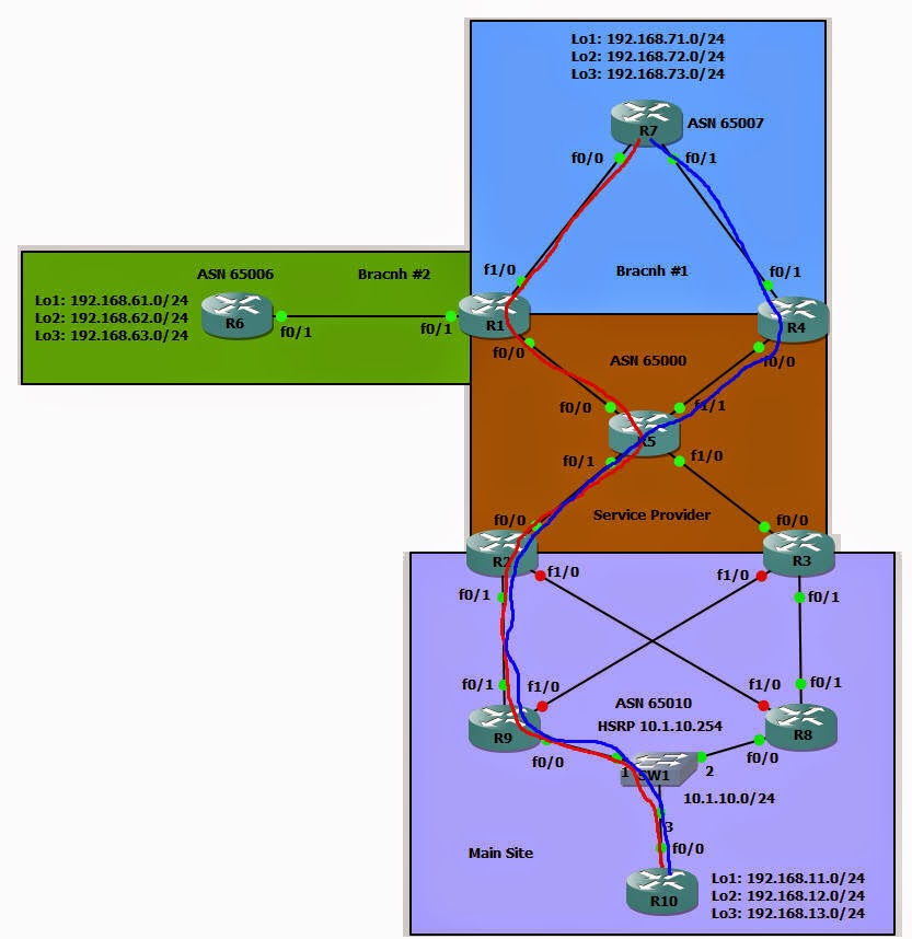
We can see that first flow will go through R7->R1->R5->R2->R9
(marked in red) and the second flow will go through R7->R4->R5->R2->R9
(marked in blue)
So we only managed to get load-share on the exit point of R7
but the traffic will reach R10 networks always through R9!
Let’s look on R1 BGP vpnv4 table:
|
R1#show ip
bgp vpnv4 vrf RED
BGP table
version is 28, local router ID is 1.1.1.1
Status
codes: s suppressed, d damped, h history, * valid, > best, i - internal,
r RIB-failure, S Stale, m
multipath, b backup-path, f RT-Filter,
x best-external, a
additional-path, c RIB-compressed,
Origin
codes: i - IGP, e - EGP, ? - incomplete
RPKI
validation codes: V valid, I invalid, N Not found
Network Next Hop Metric LocPrf Weight Path
Route
Distinguisher: 1:100 (default for vrf RED)
0.0.0.0 0.0.0.0 0 i
* i 192.168.11.0 3.3.3.3 0 100
0 65010 ?
*>i 2.2.2.2 0 100
0 65010 ?
* i 192.168.12.0 3.3.3.3 0 100
0 65010 ?
*>i 2.2.2.2 0 100
0 65010 ?
* i 192.168.13.0 3.3.3.3 0
100 0 65010 ?
*>i 2.2.2.2 0 100
0 65010 ?
<OUTPUT_OMMITED>
|
We can see clearly that we have the same problem on the PE
routers which follow the BGP best path selection rules and select only 1 best
path per prefix.
Let’s fix this problem by issuing the following command on
all PE routers:
|
Rx#conf t
Enter configuration commands,
one per line. End with CNTL/Z.
Rx(config)#router bgp 65000
Rx(config-router)#address-family
ipv4 vrf RED
Rx(config-router-af)#maximum-paths
eibgp 4
|
Note that this time I used ‘eibgp’ parameter on the command
maximum-paths to allow multi-paths from eBGP and iBGP.
Now let’s look again on R1 BGP vpnv4 table:
|
R1#show ip
bgp vpnv4 vrf RED
BGP table
version is 34, local router ID is 1.1.1.1
Status
codes: s suppressed, d damped, h history, * valid, > best, i - internal,
r RIB-failure, S Stale, m
multipath, b backup-path, f RT-Filter,
x best-external, a
additional-path, c RIB-compressed,
Origin
codes: i - IGP, e - EGP, ? - incomplete
RPKI
validation codes: V valid, I invalid, N Not found
Network Next Hop Metric LocPrf Weight Path
Route
Distinguisher: 1:100 (default for vrf RED)
0.0.0.0 0.0.0.0 0 i
*mi 192.168.11.0 3.3.3.3 0 100
0 65010 ?
*>i 2.2.2.2 0 100
0 65010 ?
*mi 192.168.12.0 3.3.3.3 0 100
0 65010 ?
*>i 2.2.2.2 0 100
0 65010 ?
*mi 192.168.13.0 3.3.3.3 0 100
0 65010 ?
*>i 2.2.2.2 0 100
0 65010 ?
<OUTPUT_OMMITED>
|
Now we got the required result:

Currently I’m using IOS 15.3 and the command ‘show ip cef
<PREFIX> internal’ doesn’t show the hash table as in version 12.3, so
after doing a little search I found this following command which state where
each source and destination exit point:
|
R9#show ip
cef exact-route 192.168.11.1 192.168.71.1
192.168.11.1
-> 192.168.71.1 => IP adj out of FastEthernet1/0, addr 10.1.39.3
R9#show ip
cef exact-route 192.168.12.1 192.168.71.1
192.168.12.1
-> 192.168.71.1 => IP adj out of FastEthernet1/0, addr 10.1.39.3
R9#show ip
cef exact-route 192.168.13.1 192.168.71.1
192.168.13.1
-> 192.168.71.1 => IP adj out of FastEthernet0/1, addr 10.1.29.2
R9#show ip
cef exact-route 192.168.13.1 192.168.72.1
192.168.13.1
-> 192.168.72.1 => IP adj out of FastEthernet0/1, addr 10.1.29.2
R9#show ip
cef exact-route 192.168.13.1 192.168.73.1
192.168.13.1
-> 192.168.73.1 => IP adj out of FastEthernet1/0, addr 10.1.39.3
|
R9 will use interface Fa0/1 (hence through R2) for source
192.168.13.1 to destination 192.168.71.1 and interface Fa 1/0 (through R3) for
source 192.168.13.1 to destination 192.168.73.1.
